Distance sensing with Raspberry Pi and an HC-SR04 sensor
I randomly selected this HC-SR04 distance sensor from a “45 in 1 sensor set” I bought, with the idea to try out the GPIO pins available on the Raspberry Pi. After some tinkering, I got a rudimentary setup and some sensor readouts. We’ll start with explaining how to wire the sensor with the Raspberry Pi, provide python code for the distance measurements followed by some oscilloscope measured signals and their discussion.
Bill of Materials
- HC-SR04 sensor
- Resistors: $1.5k\Omega$, $2.2k\Omega$
- Raspberry Pi
- Breadboard
- jumper cables
HC-SR04, a Distance sensor
The HC-SR04 is an ultrasonic distance sensor, it uses sound waves to measure distance. I would be happy to reference to a datasheet, but to my surprise, it was difficult to find one. Information seems really scattered all over the internet. As much information as possible will be consolidated on this page so you have it all in one place. And, if you think something might be incomplete or incorrect, don’t hesitate to put your questions or remarks in the comments section below! All used references will be added to the references section below.
The figure below shows the front side of the sensor.
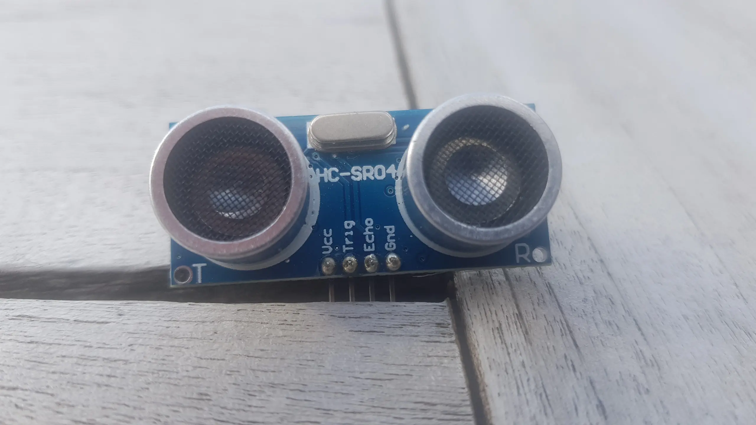
On the left lower-side of the board, we notice a “T” and the right lower-side, we notice an “R”. By deduction, these should stand for Transmitter and Receiver respectively. The transmitter will send the sound pulse and the receiver side will capture it after it has bounced off the surface to which the distance is measured.
4 pins can be seen, Vcc, Trig, Echo and Gnd.
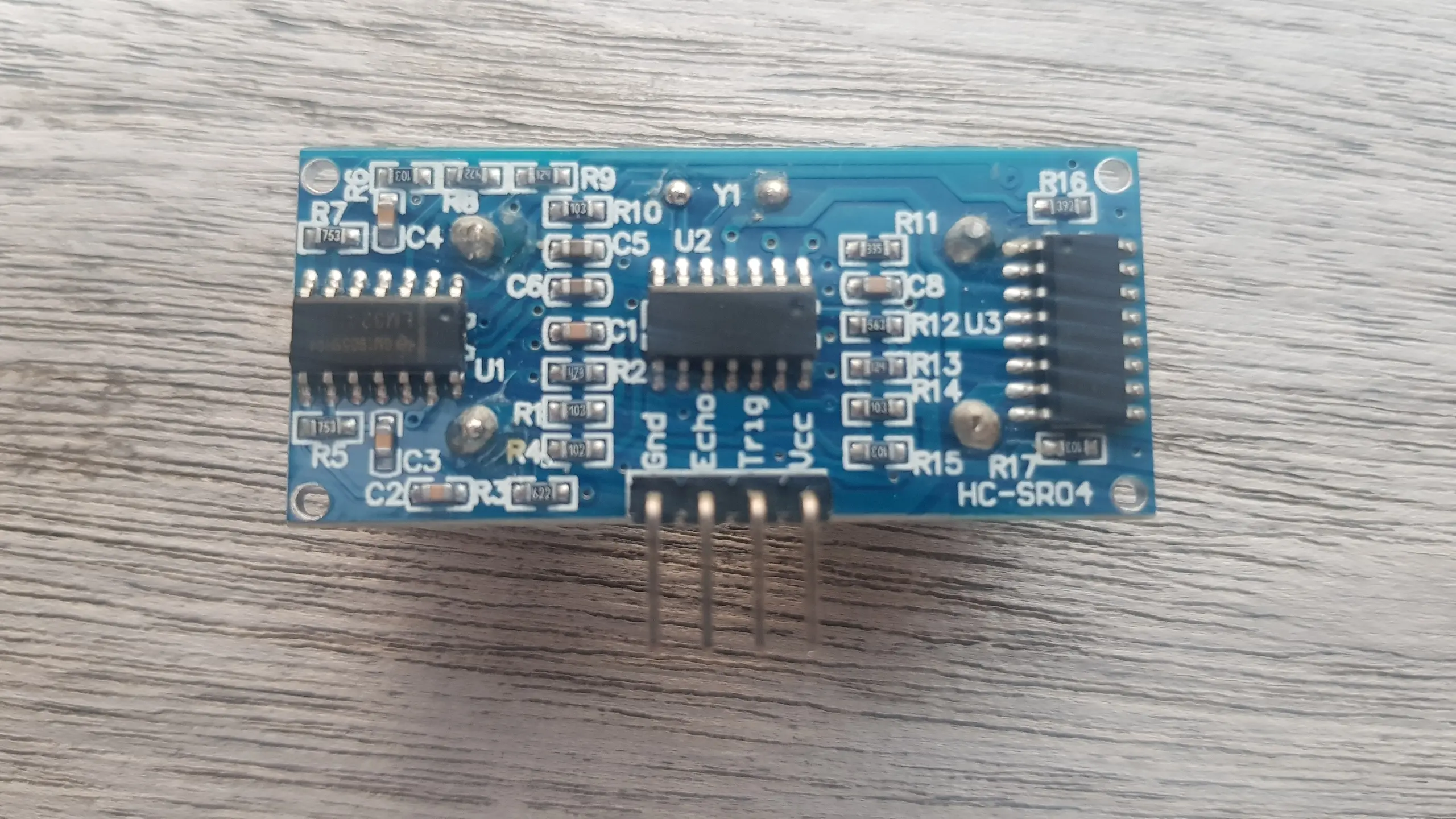
The image below shows the back side of the HC-SR04.
The voltage of Vcc depends on whether you are using an older or newer sensor. The older version seems to be requiring a $5V$ power supply, whereas the newer component could be run with a $3.3V$ power supply. You can find the differentiation of the older vs the newer component in the image below. It took me an AliExpress site [1] to discover this.
| Older component (5V) | Newer component (3.3V - 5V) |
|---|---|
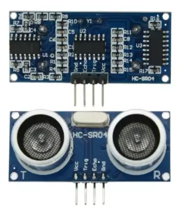 |  |
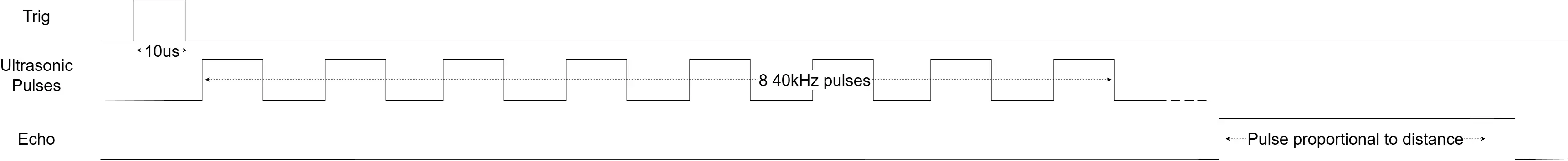
The Trig and Echo pin are both related to the functionality of the echolocation. According to [2], the module can be triggered to the Trig pin to emit a sonar wave consisting of a series of 8 pulses at 40kHz. When an object is in front of the transmitter, the wave will reflect and arrive at the receiver, which will in turn trigger the Echo pin.
Connecting the HC-SR04 to the Raspberry Pi
We ultimately need to connect the 4 pins of this sensor to the Raspberry Pi. I like to start out by referencing [3] which gives a clear view of the 40-pin GPIO header that is installed on the Raspberry Pi board. I like starting out by connecting the $Gnd$ and $V_{cc}$ pins. The $Gnd$ pin will be connected to pin 6 and since the Vcc is required to be connected to $5V$, I’ll be connecting this one to pin 2. In [2] they mention how the $V_{cc}$ pin should be brought up after the $Gnd$ pin is connected. I’m not quite sure if this is a typical behavior when starting up the raspberry Pi. However, if you are still on a breadboard, you could manually enforce this behavior by disconnecting and reconnecting the $V_{cc}$ pin to ascertain this.
The Trig pin of the sensor is connected to some available GPIO pin, like GPIO17, available on pin 11. We notice how Raspberry Pi GPIO pins can only be set to high ($3.3V$) or low ($0V$) [3]. Since [4] indicates the trigger input signal should be a TTL pulse, every voltage above $2V$ could be considered as high.
The Echo pin is also connected to an available GPIO pin, here GPIO27, or pin 13 on the header was chosen for this connection. However the connection happens indirectly in this case! The Echo pin is an output pin, and, whenever this pin is driven high, it will be pulled up to the voltage of its Vcc pin. So in this case it will be pulled up to $5V$ and you must not connect this to a Raspberry Pi GPIO pin, which is only able to handle a maximum of $3.3V$. A voltage divider (using resistors R1 and R2) is used to keep the voltage in the safe zone.
The final schematics can be seen in the image below.
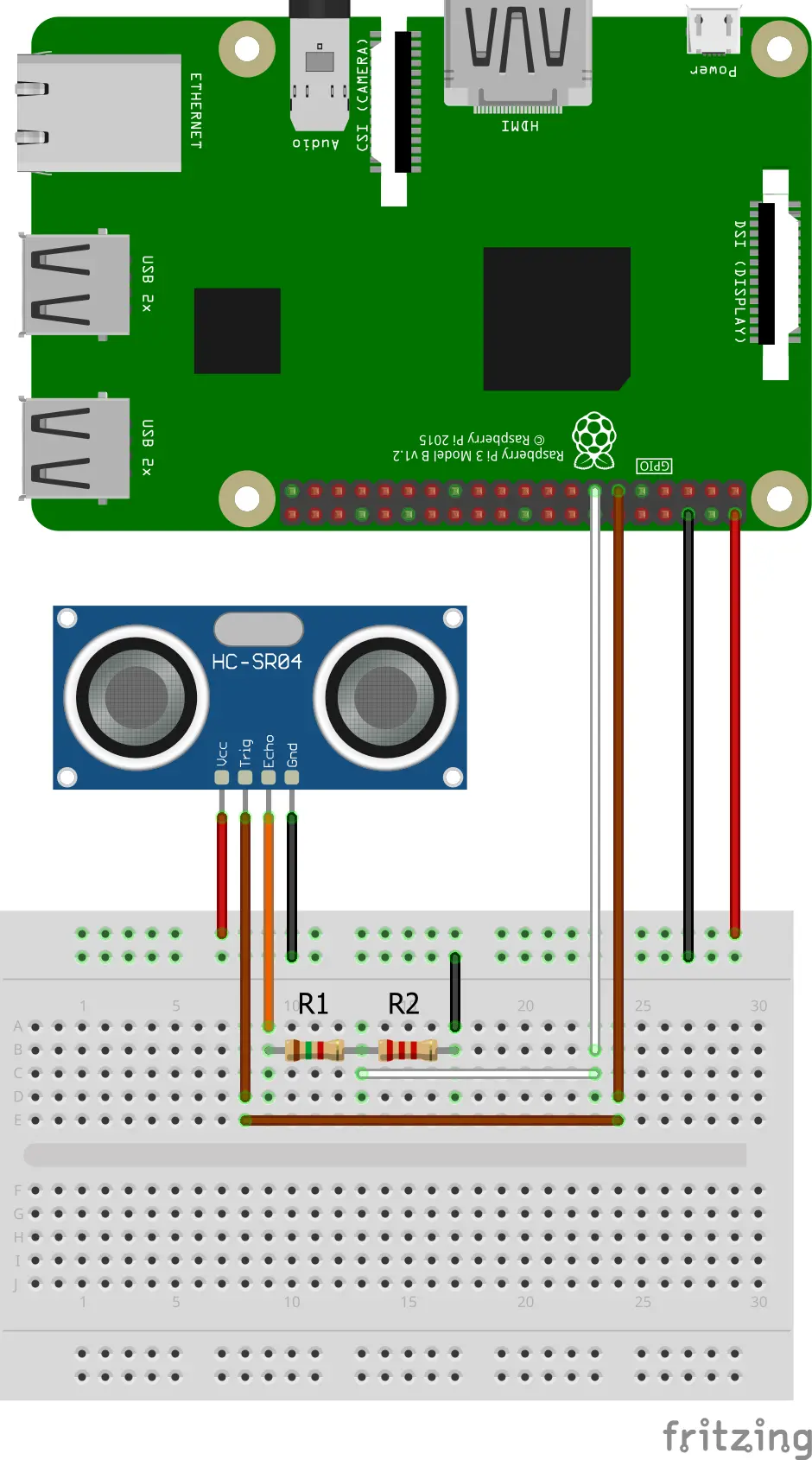
Using the formula for the voltage divider, we get: $V_{R2} = \frac{R2}{R1+R2}V_{Echo}$. An $R1 = 1.5k\Omega$ and an $R2 = 2.2k\Omega$, results in $V_{R2} \approx 0.595V_{Echo}$, so when $V_{Echo} = 5V$, we will have a maximum of $V_{R2} \approx 2.97V$. A voltage well below the maximum of $3.3V$ and high enough to be seen as a logical 1 by the GPIO pin.
Raspberry Pi Code
Now that we have our hardware all set up, we can start to write the necessary code to interface the distance sensor. Python and the RPi.GPIO module [5] were used as an easy way into getting some initial results from this sensor. The code can be seen hereafter and its discussed right after:
Python
#!/usr/bin/env python3

import RPi.GPIO as GPIO
import time

pin_trig = 11
pin_echo = 13
time_sleep_next_measurement = 60E-3

def trigger_pin_trig():
	#Set the trig pin high for 10us
	GPIO.output(pin_trig, GPIO.LOW)
	time.sleep(5E-6)
	GPIO.output(pin_trig, GPIO.HIGH)
	time.sleep(10E-6)
	GPIO.output(pin_trig, GPIO.LOW)

def read_echo_duration():
	start = GPIO.wait_for_edge(pin_echo, GPIO.RISING, timeout=1000)
	if start is None:
		print("Timeout occurred")
		return None
	t0=time.time()

	end = GPIO.wait_for_edge(pin_echo, GPIO.FALLING, timeout=1000)
	if end is None:
		print("Timeout occurred")
		return None
	t1=time.time()

	return t1-t0

def calculate_distance_cm(elapsed_time):
	return (elapsed_time*343/2)*100

GPIO.setwarnings(False)
GPIO.setmode(GPIO.BOARD)
GPIO.setup(pin_trig, GPIO.OUT, initial=GPIO.LOW) #Trig initially low
GPIO.setup(pin_echo, GPIO.IN) #Echo

time.sleep(1)

try:
	while True:
		#Allow some time between measurements
		time.sleep(time_sleep_next_measurement)

		trigger_pin_trig()

		echo_duration = read_echo_duration()
		if echo_duration is None:
			continue

		print("cm: ", calculate_distance_cm(echo_duration))

except KeyboardInterrupt:
	print("\nMeasurement stopped")

finally:
	print("Program ending...")
	print("Cleaning up GPIO...")
	GPIO.cleanup()
	print("Cleaned up GPIO")
	print("Program ended")
Code discussion
What we have here is an endless while-loop that is continuously printing the measured distance by the sensor. In order to start a measurement, we need to trigger the Trig pin using a pulse for 10us. The sensor will then send 8 ultrasonic pulses which it uses to detect if they get reflected back. As soon as the reflection is detected, the sensor will pull the Echo pin high for a duration proportional to the time it took for the detection of the reflected pulses.
The calculate_distance_cm() function then calculates the distance in centimeters. Knowing that the speed of sound is 343 $m/s$ and the elapsed_time is in seconds, the distance is simply how long the sound pulse traveled back and forth between transmission and reception. Since the time in flight of the ultrasonic pulses is back and forth, you still need the division by 2. The multiplication by 100 is then simply to convert the meters in centimeters, so:
$d = \frac{t_{elapsed}.v_{sound}}{2}$
The practical measurement range for the HC-SR04 is about 2 cm to 400 cm. Distances below 2 cm fall within the sensor’s “blind zone” due to transducer ringing, and readings above 4 m often become unreliable as the reflected signal weakens.
Waveform measurements
So this after the breadboard was set up and the code was running, I started measuring the waveforms. These provided some further insights, which complemented or validated some of the information found in the datasheets. These waveforms can be seen in the next figure.
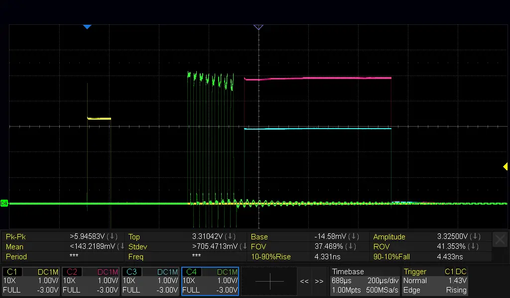
We distinguish the following signals:
- The yellow signal corresponds to the trigger pulse.
- the purple signal was measured directly on the Echo pin and the blue signal represents the voltage divided Echo pin signal.
- The green signal was measured directly on the connection of the transmitter with the PCB. We can clearly identify 8 electrical pulses that will be transformed into the 8 40kHz ultrasonic pulses.
In the following subsections, some of these signals were characterized.
Trigger pulse
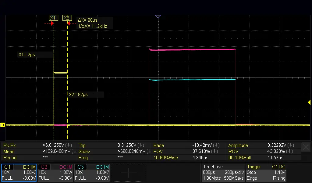
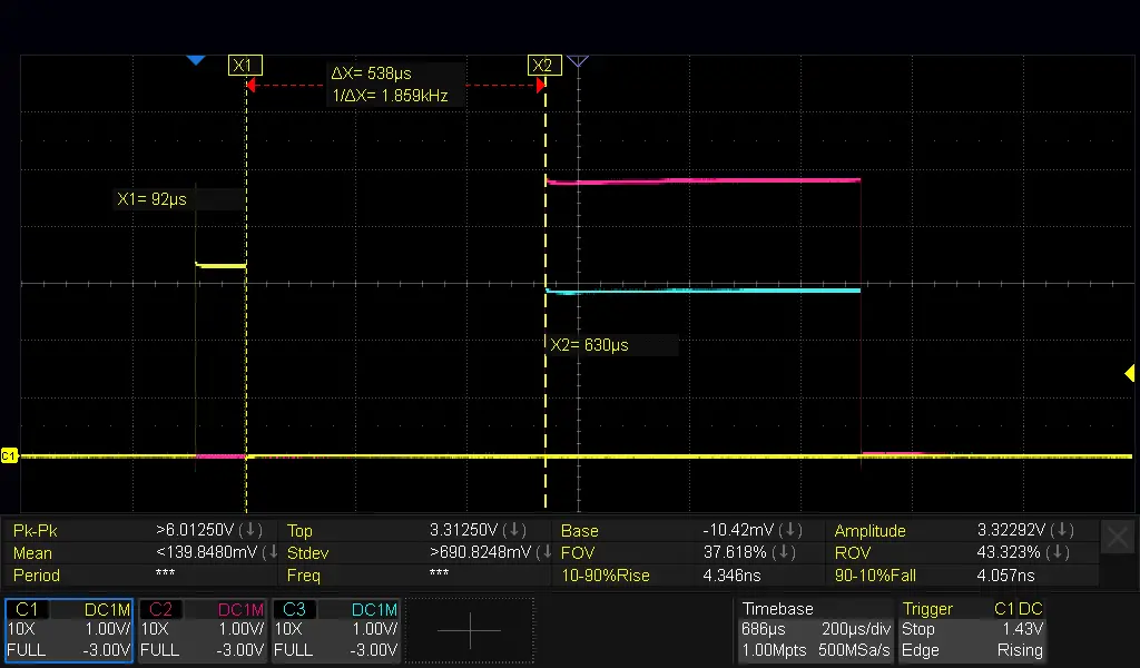
The trigger pulse is not strictly linked to the behaviour of the sensor component itself, but rather the python code running on a Linux OS on my Raspberry Pi. According to the code above, you could expect that the trigger pin is only pulled high for 10us. However, what we see in the following figure, is, that the trigger pulse is actually about 90us wide. This introduces an order-of-magnitude error compared to the 10us theoretical pulse. So, care to be taken in assuming that the trigger pulse would be exactly 10us.
Sensor “dead time” between trigger pulse and echo pulse
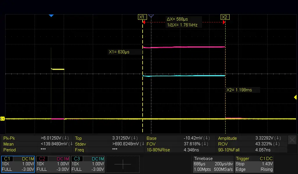
In the next figure, we see latency of around 538us between the echo trigger and the start of the echo pulse. During this period, the sonic pulses are sent. This latency did not appear to change in function of the measured distance.
Echo pulse width
The echo pulse width was 568us, and using the formula above, the distance corresponds to 9.7cm, whereas my python code returned a measured distance of about 9cm. Nevertheless, given the deviation of the trigger pulse we measured vs the theoretical value, we might doubt the correctness of the calculated pulse width in python. Certainly something that could be explored later.
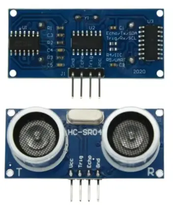
Pulse heights
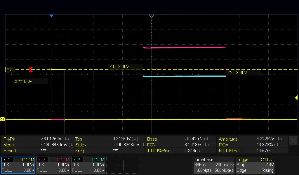
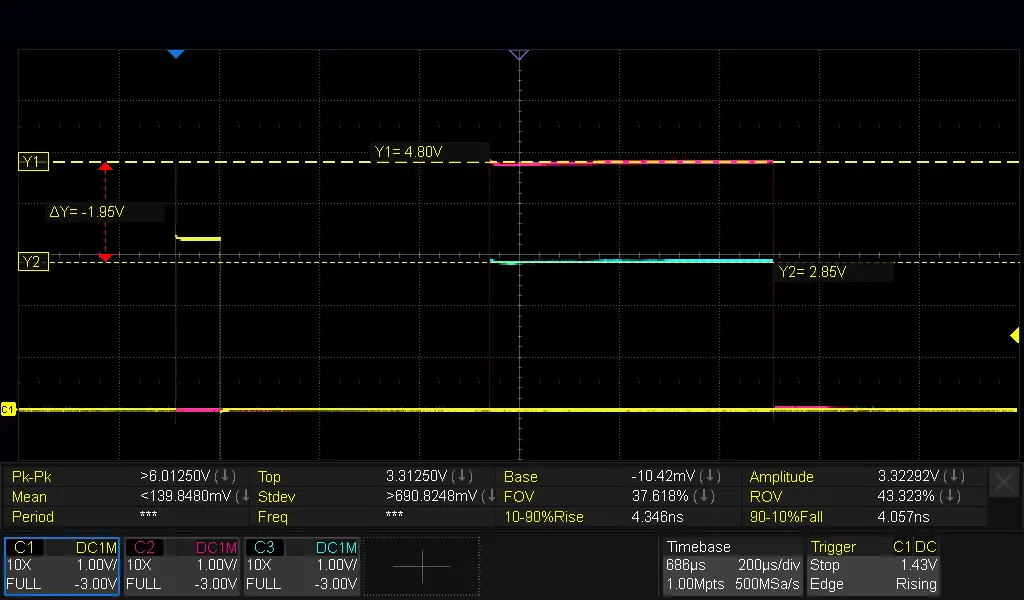
In the figure below, we see the voltage levels of the trigger and (voltage divided) echo pulses. The trigger pulse is a clear 3.3V signal as could be expected. The Echo pulse at the Echo pin does not go up to the 5V rail, but settles at 4.80V, so we see a small voltage drop, nothing out of the ordinary. And the voltage divided echo pulse settles at 2.85V, which is about the voltage level expected (cf. above $V_{R2} \approx 0.595V_{Echo}$).
| Trigger Pulse | Echo Pulse |
|---|---|
 |  |
Sensor calibration
It could be useful to think about calibrating the sensor, but that might be a subject for another post. Also, the speed of sound is a function of temperature and humidity. The 343 $m/s$ might therefore need to be compensated as well.
Also, this sensor might be sensitive to background 40kHz noise. Therefore, if using multiple of these sensors, it might be best to trigger them sequentially.
Noteworthy
I encountered a comment from a reader indicating that the sensor can be used for measuring the liquid level in a container. Nevertheless, when the container was sealed off, with the sensor inside, condensation could form on the reader, affecting accurate readouts. I did not experiment with this, but, if you would like to use it this way, it might be worth considering. Please note that there are some other, condensation and splash water proof distance sensors like the JSN-SR04T
Useful references
- [1]: Ali Express product page comparing 5V and 3.3V versions of HC-SR04 Shows the difference between 5V and the 3.3V-5V version.
- [2]: Shop page with HC-SR04 specs and behavior
- [3]: Raspberry Pi GPIO pinout documentation
- [4]: What looks to me like an unofficial datasheet
- [5]: RPI.GPIO - a package that provides a Python module to control the GPIO on a Rapsberry Pi