Wondering about a Pico 2 scope functionality
Can a Raspberry Pi Pico 2 act as a rudimentary oscilloscope? After successfully streaming data from my Pico 2 device into a python application over USB (read about it here) and knowing the RP2350 contains an ADC, I was enthusiastic to find out whether I would be able to visualize the echo pulse from an ultrasonic distance sensor, the HC-SR04. I started out trying to maximize the USB throughput and image refresh rate, only to be confronted with some limitations I might cover in some follow-up posts. This post will focus on an initial and more pragmatic measurement and plotting setup, grounded in some theory about the RP2350’s ADC behaviour and the echo pulse charateristics.
Some theory
As promised, some theory. Let’s start with the echo pulse we would like to measure, followed by the ADC behaviour.
HC-SR04 Echo Pulse
The ultrasonic distance sensor HC-SR04’s echo pulse width is measured as this provides the necessary information to calculate the distance. Here, I was more interested in the pulse widths we could expect as a function of distance, which can be calculated as follows:
$t = \frac{2d}{v_{sound}}$, where $v_{sound}$ is the speed of sound (343m/s), d, the distance and t is the pulse width.
So for each centimeter increase in distance, the pulse widens about 58.3 us. For convenience, hereafter a couple of values in between the practical measurement ranges of 2 cm and 400 cm:
| d [cm] | t [ms] |
|---|---|
| 2 | ~0.117 |
| 5 | ~0.292 |
| 10 | ~0.583 |
| 20 | ~1.166 |
| 50 | ~2.915 |
| 100 | ~5.831 |
| 400 | ~23.324 |
We see how for distances of 2 cm and 400 cm, the respective echo pulse widths are respectively 117 us and 23.324 ms. So for short distances, the pulse is already really narrow and ideally we should be able to sample faster than the narrowest pulses.
ADC
When looking at the specification of the RP2350’s ADC, we mainly notice how 96 cycles are needed for a conversion. For a typical clock frequency of 48MHz, this leads to a conversion time of 2us per sample. So in theory we could measure every 2us for a total of 500kSamples/s, in practice this means we would need to be able to move this data off the device at a high enough throughput. Now, its possible to reduce the sample rate by setting the DIV.INT to a positive value n. As per the datasheet, it will trigger a new ADC conversion every n + 1 cycles. So for a couple of values of n and a clock of 48 MHz, we have the following table. Since in my code, the sample size is also 32 bit (most likely not yet fully optimized), I can generate the following table containing the sample period, kSamples/s and throughput for different values of n:
| n | Sample period [us] | kSamples/s | Throughput [Mbit/s] |
|---|---|---|---|
| 95 | 2 | 500 | 16 |
| 767 | 16 | 62500 | 2 |
| 1199 | 25 | 40000 | 1.28 |
| 5999 | 125 | 8000 | 0.256 |
| 11999 | 250 | 4000 | 0.128 |
| 23999 | 500 | 2 | 0.064 |
The 32 bit per sample is more a residue of my DMA and USB transfers which don’t feel fully optimized yet (Please, drop a comment below if you would already know if I could simply limit the DMA to 16bits for my ADC samples). For the moment, I’m settling with that. Another choice, I’m taking here is to set n to 5999, which does provide me a sample period of 125us (so, every 125us a trigger is given to the ADC to initiate a conversion). Given that the echo pulse is about 292us for a distance of 5 cm, I expect that I should reliably see the echo pulses for these and higher distances since with a sample period of 125 us, we should have 2 or 3 samples to detect this peak. We could of course select the highest sample rate of 2 us and be certain to catch even the narrowest pulse, but this sample rate revealed the limitations I mentioned in this article’s introduction (and which will be discussed or even corrected in following posts): one, was the limitation of the USB throughput and another was missing measured echo pulses. The theoretical required USB throughput of 0.256 Mbit/s for this setting felt highly achievable through testing.
Setup
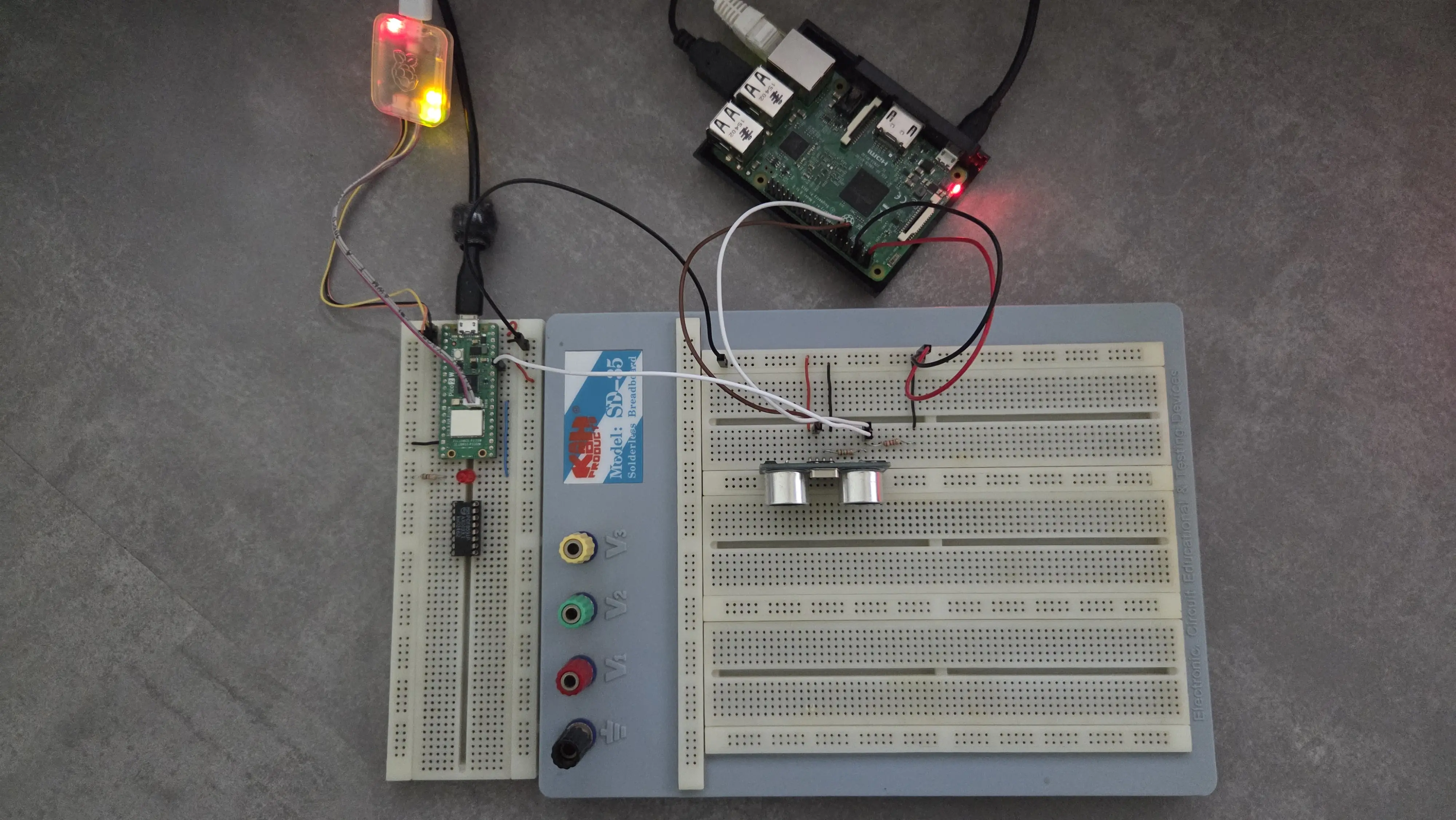
In order to measure the echo pulses, I have reused the setup I described in one of my earlier posts: A HC-SR04 ultrasonic distance sensor, requested to perform a measurement every second through a python script on a Raspberry Pi. I connected an ADC pin of my Pico 2 to voltage divided echo pin (since the HC-SR04 outputs 5V, a voltage divider is needed to safely connect this to the Pico’s 3.3V ADC input pin). The measured samples are then streamed over USB to a python application running on a host PC. An overview of the Pico 2 connected to the HC-SR04 setup can be seen below:
Running the test
So when running the application on my host PC, I did get the following images:
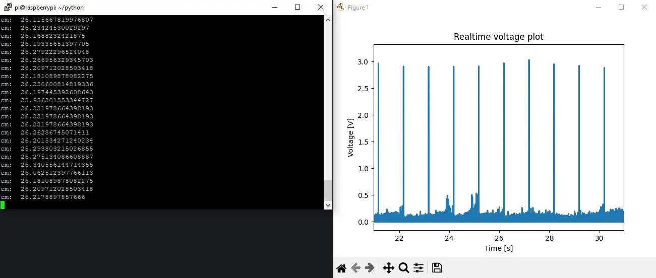
On the left, we see the output of the python script running on the Raspberry Pi, which returns the measured distance. In the image on the right, we see a peak to about 3V every second, which represents the echo pulse.
Zooming in on one of those pulses, we have the image below:
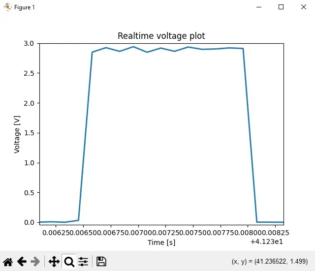
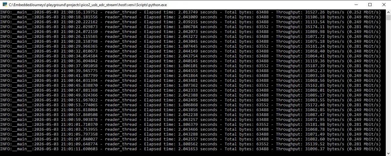
Checking for the width of this pulse, I obtained 1.498ms, which according to the formula above, corresponds to a distance of ~25.6907cm. This closely matches the ~26cm reported by the sensor, confirming that the ADC measurement is working as expected. Interestingly, the measured USB throughput (~0.250Mbit/s) closely matches the theoretical value for this sampling configuration. This suggests, at this stage, the system behaves largely as expected.
Source code
The source code of this experiment will be published shortly.
Want to get started quickly?
I have also packaged firmware, source code, a Python host application and quick-start guide to achieve 5.1 Mbps USB streaming on the Pico 2 into a downloadable reference implementation. Feel free to check it out.
Future work
These initial results show that the Pico 2 can indeed capture some real-world signals. However, when increasing the sample rate, things start breaking down: echo pulses go missing, throughput gets throttled by the plotting of the host… In the next post, I’ll dive into why this happens and explore how to fix it.
comments powered by Disqus